
- #Same counter count up and down logix pro 500 series#
- #Same counter count up and down logix pro 500 simulator#
The preset value is the number of counts that should occur before Therefore,įor this example we will use C5:0, the first counter in the file.

Counters are stored, by default, in data file #5 and use a fileĭesignator of ‘C’. Output instructionsĬan be placed in series, but incorrect operation can occur.Ĭount Up Counters (CTU) – SLC500s & LogixProĬounters have three instruction parameters: Multiple outputs on the same rung should be placed in branches. In LogixPro the output instruction should be placed against the right power rail and With multiple outputs on the same rung being branched. In the ControlLogix platform output devices are also placed against the right power rail With multiple output instructions on the same rung being placed in branches.

#Same counter count up and down logix pro 500 series#
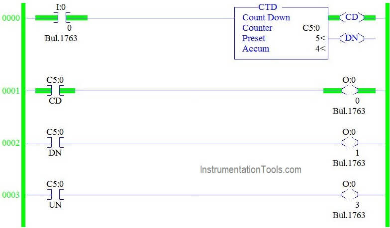
Output instructions in the SLC500 series are always placed against the right power rail Will always be placed against the right power rail. The HSC is only available in selected AB Micrologix series controllersĬounter instructions are output instructions therefore they CTD – Count Down (SLC500’s/Micrologix, ControlLogix & LogixPro) CTU – Count Up (SLC500’s/Micrologix, ControlLogix & LogixPro)
#Same counter count up and down logix pro 500 simulator#
The SLC-500/Micrologix series has three counters andĬontrolLogix and LogixPro Simulator has two counters: SLC-500’s/ControlLogix & LogixPro Counters Note: User defined files are not available in LogixPro Used when communications is required between early AB PLCs It is called the “Computer Interface File” (CIF) and is Value or to count down to a preset value. PLC counters can be designed to count up to a preset Is activated at the time of power restoration. The counter can be reset on power-up if the reset condition Processor shutdown will be restored to the counter on power-up. Whatever count was contained in the counter at the time of a They are dependent onĮxternal sources such as parts traveling past a sensor or The number of items moving past a given point, orĭetermining the number of times a given action occurs.Įlectronic counters can count up, count down, or beĬombined to count up and down. The entire 32-bits of the preset and accumulator words are used, this is why the preset and accumulator numeric range is: -2,147,483,648 to 2,147,483,647.Ĭommon applications of counters include keeping track of The upper 16-bits (bits 16 to 31) of word 0 are not used. The counter memory in the LogixPro simulator is 32-bit. The memory block depicted on this slide shows 16-bits.


 0 kommentar(er)
